Okay, this is my first try to make some kind of classification of digital equalizers. It’s mostly based on some defects or features they have in their responses. These defects or features give digital equalizers their unique sound. Sometimes they sound “digital” in bad meaning of this word (i.e. “harsh”) but the other side of digital sound is clean, pristine and maybe too cold sometimes. I don’t have much time to make this classification really glossy so it’s some kind of a draft.
In my opinion there’re 7 main properties of digital equalizers, which affect their sound:
- Frequency response behavior near Nyquist frequency
- Phase response behavior near Nyquist frequency
- Frequency response ringing
- Types of Curves
- Time domain response
- Saturation
- Noise
Now I’m going to try to illustrate possible cases for each property by some images mostly created by VST Plugin Analyzer. All pictures were created at 44.1 kHz sample rate. Also I do not mention real plugin names used.
1. Frequency Response Behavior Near Nyquist Frequency
1-a) “Cramping”
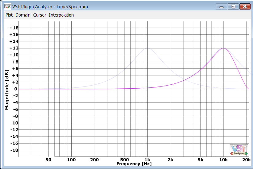
Check this picture. There’s a typical 1 kHz peaking curve. Also I shifted this curve using copy and paste in an image editor to show how it’d look for 10 kHz.
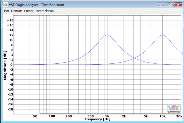
Now if someone has implemented cool EQ using equations from “Cookbook formulae for audio EQ biquad filter coefficients” by Robert Bristow-Johnson (RBJ) the curve at 10 kHz could have this kind of a look:
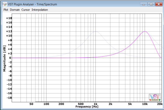
So you can see the right side of the bell shape is distorted. Well it sounds like high Q harsh boost. There’re ways to mathematically match Q at 10 kHz with Q at 1 kHz but the shape distortion remains and such distortion has its own “digital” sound.
There’s nothing bad with RBJ, it’s just a side effect of bilinear transform (BLT) used to create digital infinite impulse response (IIR) filter from its analog prototype. This transform used very widely and shape distortions are acceptable for frequencies below 1/3 of Nyquist.
By the way, the initial 1 kHz bell was created using bilinear transform too. If you take a closer look now you may notice it’s a bit asymmetric too (check curve crossings at 200 Hz and 5 kHz for example) but this asymmetry is pretty much acceptable.
Some links:
http://www.musicdsp.org/files/Audio-EQ-Cookbook.txt
https://www.gearslutz.com/board/10578791-post373.html
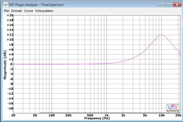
1-b) “Decramping”
“Decramping” is some kind of compensation added to IIR filter calculated by BLT to make its amplitude response more analog matched at high frequencies. They look much better but nevertheless they have their own kind of shape distortion: the amplitude response curve enters Nyquist frequency horizontally.

Speaking of sound decramped filters sound much more gentle for high frequencies than cramped ones. The shape distortion is insignificant. The only problem with “analog matching” for such filters is their phase response is not analog matched at all.
Some links:
S.J. Orfanidis, “Digital Parametric Equalizer Design with Prescribed Nyquist-Frequency Gain” (AES paper)
M. Massberg, “Digital Low-Pass Filter Design with Analog-Matched Magnitude Response” (AES paper)
Dan Worall description about “phase natural” mode
1-c) Bandwidth Limiting
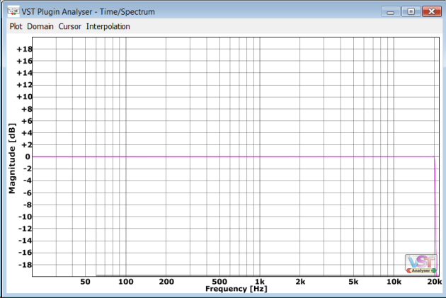
A digital equalizer can limit bandwidth for some reasons (usually due to oversampling used). In most cases it looks like very sharp low-pass filter above 20 kHz or very close to Nyquist.
Here are some real world examples:


How does this sharp bandwidth limiting sound? Well, for me it moves a sound a bit far away. Sharp filters have long ringing in their responses, which smear transients and makes a sound a bit distant. But don’t be scared too much. All AD/DA converters have sharp low-pass filters for anti-aliasing or anti-imaging reasons so you can think of this process as passing the sound through external analog gear. Different converters may have different filters by the way.
But also the smooth bandwidth limiting may appear when transformer modeling is used in a plugin. Such bandwidth limiting usually looks like 12 dB/Oct low-pass at 30-35 kHz.
Also some equalizers may limit bandwidth at low frequencies to block 0 Hz (DC).
Some links:
http://lavryengineering.com/pdfs/lavry-sampling-theory.pdf
http://lavryengineering.com/pdfs/lavry-sampling-oversampling-imaging-aliasing.pdf
2. Phase response behavior near Nyquist
2-a) Phase Slowly Goes to Zero
A digital equalizer must have phase of zero at Nyquist frequency. That’s some kind of a law. The most “natural” digital phase behavior for phase minimum filter is to slowly approach to zero near Nyquist.
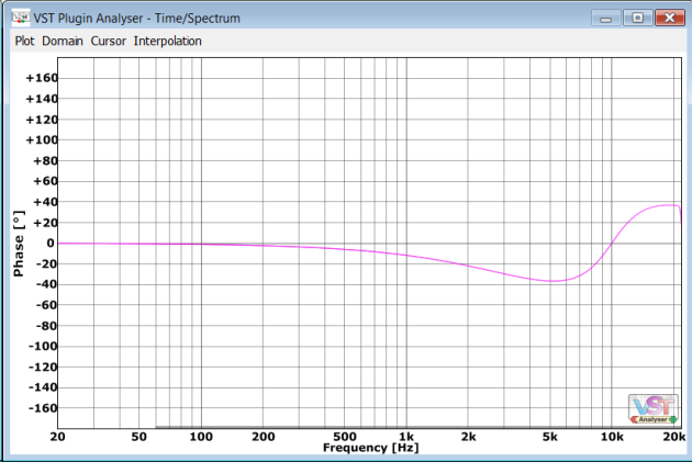
Let’s check digital amplitude and phase response for “cramped” filters:


And this is a typical amplitude and phase responses for “decramped” filters:


What so special about phase response of an equalizer by the way? The answer is simple. The phase response gives a “color” to the sound.
Some links:
http://varietyofsound.wordpress.com/2010/02/05/about-audio-signal-coloration/
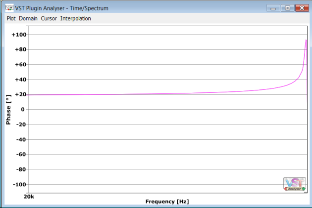
2-b) Analog Phase Matching as High as Possible
I like the word “natural” to call analog matched phase response by the way. Okay, in some ideal case for a filter response like this:

The full analog matched phase response must be this:

Does it break some law? No. Even in this filter the phase response at Nyquist is zero but the jump from analog matched phase value to 0 is so fast so it’s less than precision of VST Plugin Analyzer.
Most “natural” phase real world equalizers have responses like these:
Some links:
Dan Worall description about “phase natural” mode
2-c) Phase Discontinuity
In some equalizers there’s so fast jump from smooth phase analog matched response to zero so it creates some kind of “break” or “discontinuity” in a curve. The side effect of this discontinuity is some kind of “ringing” of phase response on the sides of this breaking point.
For example take a look at this phase response:
It has very small amount of phase response ringing visible if I magnify the response:

An ear can’t perceive such small amount of ringing but in some cases more obvious ringing is possible (I don’t have good examples nearby).
2-d) Phasy Bandwidth Limiting
This often happens when min-phase oversampling is used. Oversampling can be used as a way to avoid cramping effects and min-phase oversampling can be used to maintain zero latency.
Check this response for an equalizer with all band gains set to zero:

But this almost straight amplitude response has this kind of phase response:

How does it sound? Well, an ear doesn’t perceive actually phase response, it’s sensible to group delay instead. Group delay response shows how much each frequency is delayed. Group delay and phase response can be calculated from each other. Now check the group delay graph for the phase response above (y axis is in samples for 44.1 kHz sample rate):

You can see the high frequencies are delayed. How does it sound? For me it sounds very unnatural. It’s like looking to an audio image through some kind of a crooked glass. You’ll never achieve hi-fi sound this way.
Some links:
http://www.kvraudio.com/forum/viewtopic.php?t=394862
2-e) Linear Phase
Digital equalizers can perform linear phase. In this case both phase response graph and group delay are straight lines. Linear phase processing requires latency and leads to pre-ringing.
NOTE: VST Plugin Analyzer sometimes doesn’t recognize latency compensation from a plugin so phase response looks like a messy of lines and the horizontal line of group delay is somewhere above the graph but you can find it.
3. Frequency response ringing
3-a) Ringing at Low Frequencies
Such ringing usually occurs in finite impulse response (FIR) filters with rectangular truncation window. This ringing is usually very obvious at low frequencies.

Some links:
http://www.labbookpages.co.uk/audio/firWindowing.html
3-b) Bandlimiting Low-Pass Filter Corner
Something like this:

Filters having some amplitude response ringing usually have shorter impulse response so they smear transients less and also it reduces latency for linear phase case. It’s good to find some kind of a compromise between impulse response length and is this frequency response ringing effect audible or not.
4. Types of Curves
(no pictures here, use your imagination)
4-a) “Analog” like curves
A digital equalizer can have different types of curves, which used in analog equalizers too. For example, symmetric bells, Baxandall shelves, not so sharp LPFs and HPFs
4-b) Curves hardly possible in analog
Such curves include flat top filters, symmetric resonant shelves, more than 24 dB/Oct LPFs/HPFs, 3 dB/Oct LPFs/HPFs. Theoretically such filters are possible but it’s pretty hard to implement them in analog. There’re a lot of difficulties in analog world!
4-c) “Freehand” curves impossible in analog
Such curves include spline curves, variable slope LPFs/HPFs and so on.
4-d) Curves with artificial difference between channels
For stereo analog equalizers it’s very hard to match analog components for both channels. It leads to small changes between curves for left and right channels. Sometimes it sounds good because it widens stereo image. Some digital equalizers add small difference between channels to mimic this effect.
5. Time domain response
5-a) Pre-ringing
Pre-ringing usually can be found in linear phase equalizers. But minimum phase equalizers with linear phase oversampling have pre-ringing too. Equalizers with pre-ringing have some latency to compensate this pre-sound.
It’s very simple to create initial impulse file (all samples of zero except one sample at 0 dBFS) and to process it with an equalizer and to perform visual check does it have pre-ringing or not.

The picture above is for linear phase equalizer. Little squares on the picture mean sample values and smooth line between them is reconstructed waveform (i.e. after DA conversion).
And this is a picture for min phase equalizer with linear phase oversampling:

You may see a kind of “ringing” at frequency close to Nyquist (one sample’s up, one sample’s down and so on) but the impulse response of the filter is not symmetric this time.
This the response for an equalizer without pre-ringing at all:

You see the pre-ringing again, don’t you? But the actual sample values prior to the main peak are zeros! (check small squares left to the peak) This pre-ringing occurs only in reconstructed waveform. That’s because the natural form of a band-limited wave has ringing at a half of a sampling frequency. That’s a law so don’t bother too much about this.
Some links:
https://www.gearslutz.com/board/mastering-forum/925681-echoes-past.html
5-b) Post-ringing truncation
Analog filters have infinite post-ringing. Okay, not infinite actually but the impulse response fades down to analog noise or quantization errors in digital equivalents.
Filters inside an equalizer “ring” on their frequencies. Sharper filters have longer ringing so the ringing may become audible. The common trick is to truncate impulse response or to apply soft windowing function on it. This truncation is the main difference between IIR (infinite impulse response) filters and FIR (finite impulse response) filters.

The picture above contains impulse response of smooth 6 dB/Oct filter with hard truncation (rectangular window function). The impulse response is magnified so this “step” actually is very small.

And this picture above contains the same impulse response but with soft truncation.
The type of truncation used affects the sound in its way. Hard truncation may sound like short gated reverb added to a track and sometimes it sounds very good. And smooth truncation instead of infinite tail may work better with transients.
Some links:
https://www.gearslutz.com/board/gear-shoot-outs-sound-file-comparisons-audio-tests/823992-nebula-vs-algorithmic-eqs.html
5-c) “Managed” Ringing
Digital filters can implement some kind of managed ringing. For example check digital sample values on this picture:

Impulse samples go to zero very fast but smoothly at the same time. Such rare filters are very transient friendly.
Some references:
Peter G. Craven, “Antialias Filters and System Transient Response at High Sample Rates” (AES paper)
6. Saturation
I don’t want to say a lot about saturation. It’s a separate topic. For simplicity it’s enough to say that digital equalizer may have saturation or may not.

The saturation topic is closely related with aliasing. I usually hear aliasing as “dirt” added. To check aliasing just zoom the part of the image near Nyquist frequency.


Some links:
https://www.gearslutz.com/board/music-computers/418022-lets-do-ultimate-plugin-analysis-thread.html
7. Noise
7-a) Quantization Noise
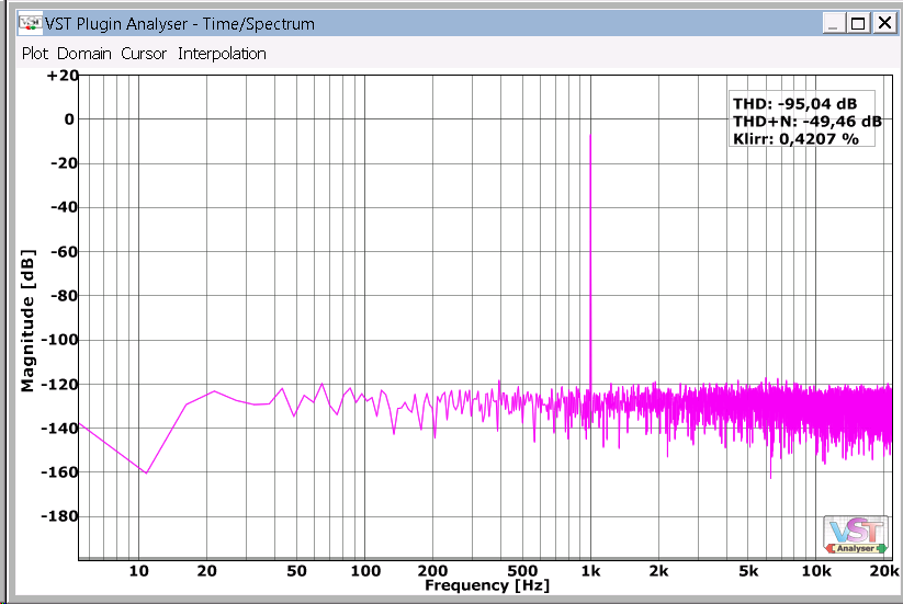
This noise occurs in digital equalizers due to limited bit-depth or limited precision in calculations. Check this picture:

The small vertical lines from the left to the right are the result of quantization errors. Usually if they are below –140 dBFS, it’s OK. Sometimes digital equalizers work at 32-bit floating point precision or less because it consumes less CPU cycles but in my opinion, 64-bit floating point precision must be used in all processing in all modern digital equalizers because a quantization noise is the thing that makes digital sound “digital” in bad meaning of this word.
Sometimes analog modeling requires solving of differential equations. To save CPU cycles the precision is often reduced and it may lead to high amount of quantization noise too:

7-b) Artificial Noise or Dithering
Often in analog modeled equalizers a noise is added to mimic the noise of analog hardware. Also this noise helps to remove quantization errors and to mask another kinds of processing artifacts and often “noisy” plugins sound not bad at all!

Some links:
http://en.wikipedia.org/wiki/Dither
Okay, I hope someone could find this text useful.


Great article, Vlad – Thanks for sharing!
Reblogged this on Variety Of Sound and commented:
A must read for EQ aficionados 🙂
Thanks Vlad for sharing!
Excellent article Vlad!! Thanks for sharing
Thanks, excellent read.
That was a good read, thanks.
Thank Vald!
QUESTION: Can you briefly explain why/how excessive FIR ‘ringing’ can ‘wrap-around’ within a window, and appear at the front of the window?
Awesome! I saved this as link, who contain more useful links. And again, thank You for Your pristine plugins! 🙂
Very nice explanation why equalizers can sound so differently. Reads like a book 😉
Reblogged this on Audio & Computer Music.
Very good writing!
Thanks a lot!
Very good summary of common obstacles in the digital filter design. Having established the problem, are there any plans to elaborate on possible solutions, especially for magnitude and phase response distortion?
Overcoming the bilinear transform limitations for the magnitude response is somewhat covered (“somewhat” because the known solutions mostly deal with design of simple filters, where the prototype filter can be adjusted (altered) before digitization which is not easily applicable if complex filter network is being digitized). But what about the phase response? Just go with the FIR filtering and deal with latency and computational cost?
Thank you for a great article!
Never heard of this ringing described in 3-a. Is this just a frequency-response artifact or does “ringing” applies to time-domain artifact?
Pingback: Some news | vladg/sound
You are great! Thanks a lot!
Pingback: Actual mastering | Jon Ville Production
Pingback: イコライザーと位相に関するアレコレをまとめてみた | SOUNDEVOTEE.NET
What the heck this is so interesting while being complex.. I am amazed by how sound and processing works. Life is crazy. Thats a good article. Tha ks for posting